RGBI to VGA via an ESp32
 RGBI?
RGBI?
Commodore 128 computers have two video chips. A VIC-II chip
variant for output in 40-column mode and C64 mode and a VDC chip
for output in a more business-like 80-column mode. While the VIC
chip output can be converted by numerous different RF/SCART/etc
adapters and upscalers, the VDC output is via a 9-pin D-SUB port
which has a signal and pin layout that is very similar to a PCs
CGA output. Actually that’s how I used to do it. I’d plug my
C128 into my Victor EGA monitor and it just worked even if some
of the colours weren’t perfect.
However, it’s now 2021 and even if I do have that monitor stored
in a closet somewhere I’d much prefer using my limited desk
space for other things. So how do you get RGBI output onto a
modern flat screen display with HDMI or VGA input?
Converting a C128 RGBI to a signal that’s usable by modern
equipment has required either daisy chaining a Gonbes GB-8200
converter with an extra converter such as the BIT-C-128 Video
DAC http://www.bit-c128.com/
or an adapter that softens up the digital signal just enough to
be able to send it to a more forgiving display that can handle
SCART or VGA with 15.7 KHz HSYNC.
A DAC + a Gonbes will set you back around 50 euros. The simple
adapter approach is cheap but requires you to get hold of a
display that can handle 15.7KHz.
So as a small project during the Christmas holidays I decided to
try and make a simple RGBI to VGA converter using one of the
many cheap low powered SoC’s that are available these days.
I ended up choosing between an ESP32 and a STM32F4xx chip and
chose the ESP32 based mainly on the fact that I found out that
someone had already made a very competent VGA output library for
it http://www.fabglib.org/.
ESP32
You’d think that this kind of 240MHz SoC would be able to handle
brute force reading it’s IO pins fast enough to handle the input
from RGBI. The RGBI output pixel clock is somewhere in the
region of 16 MHz giving you a nice cool 15 cycles to read and
store the values.
Unfortunately it turns out that to handle the ESP32s dual core setup, it uses FreeRTOS which while fixing a lot of multicore issues also inflicts a bunch of interrupts, watchdogs and other features that made reading the IO pins consistently and fast enough an impossible mission and on top of that it turns out that assembly programming isn’t very well documented due to some NDA that exists with between the companies responsible for the chip.
Suddenly 15 cycles isn’t that much... The best that someone has
been able to do is to read them at around 3.6MHz which was way
too low for my needs https://github.com/MacLeod-D/ESp32-Fast-external-IRQs
. IRQs didn’t help in improving the precision either, if
anything the interrupts that are available for C++ programs vary
even more in their timing than polling the IO directly to such a
degree that they weren’t even an option for the HSYNC signal.
It turns out that the makers of the ESP32 had already though
about this and included multiple powerful data streaming
features such as I2S, I2C, SPI etc..
So the way that FabGL solves outputting VGA fast enough is by
using a feature called parallel I2S. I2S https://en.wikipedia.org/wiki/I%C2%B2S is
actually usually used for sound transfer, but the ESP32 supports
running it in parallel on several pins so that it can read the
output from a camera
https://github.com/espressif/esp32-camera
or push data to another unit.
Not only does it support reading multiple pins at high speed. It
also supports enabling/disabling input streaming based on 3
input signals which can be mapped to HSYNC,VSYNC etc…
Luckily the ESP32 can run two I2S setups at the same time and
FabGL was only using one of them for the VGA output.
By using the parallel I2S feature in a tight loop, sampling at 32MHz, I finally managed to get a stable picture with some glitches. The glitches seem to be interference from FabGL and the loop compensates by shortening a small delay when it detects that sampling a line has taken more than the expected mount of time.
Sampling at 32MHz is probably slightly too low
but anything higher than that and my ESP32s sampling went all
wobbly :-) After double checking the ESP32 forums it turns out
that it doesn’t support sampling at a higher rate than 20MHz
when running parallel I2S, so I guess that 32MHz is pushing it
slightly…
The ESP32 doesn’t have a lot of memory (well relatively
speaking…) and only some of this is available for DMA transfer
to the I2S system. On top of that FreeRTOS grabs quite a lot of
memory and FabGL uses some as well, which doesn’t leave a lot
for my little project.
Another odd detail is the memory layout for the DMA + I2S FIFO.
RGBI is only 4 bits per sample. However, while I2S1 can push and
read 8-bit samples, I2S0 can only read 16-bit chunks from the IO
pins. So reading 640 pixels requires 2560 bytes plus a bunch of
bytes for data that’s really just the border, so there was just
enough DMA memory available for 2 screen lines of data.
In the end, after all that complaining I still think the ESP32
is a pretty impressive SoC with a nice feature set. This is a
low powered 240MHz SoC, with WiFi, Bluetooth and bunch of
features and all for around 6 euros.
The implementation
So the entire setup is basically FabGL running its I2S on core
0,
my RGBI input running I2S on core 1
and then using the residual time on core 0
to pack the 2560 bytes into a 320x200 buffer storing 2 pixels
per byte
which it then uses FabGL’s DirectVGA class to push to VGA
output.
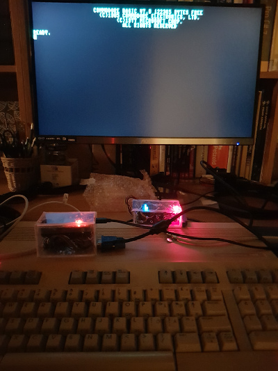
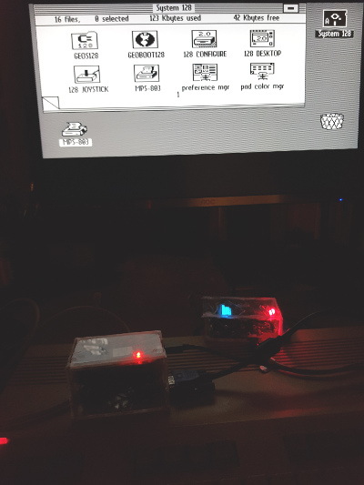
It’s pretty stable on my C128.
My C128D still has a slight flicker around the pixels but that
might just be a bad circuit in the C128D or EMI.
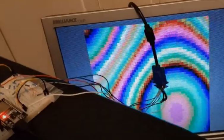
After spending all this time setting up the converter to use
640x200@70Hz VGA output on my 4:3 format display, it turns out
that my wide screen display can’t handle it and thinks that it’s
640x350. Luckily that was sort of the point of this project, so
I just adjusted the ESP32 VGA output to 640x240@60Hz for the
time being (which is why some of the picture look a bit
cramped.).
One day I will learn how to create and order PCBs, but not today
.
The code and schematics are now available on GitHub:
https://github.com/AlexMartinelle/RGBI2VGA
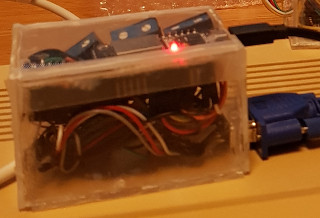
The schematic contains 11 components:
• An ESP32 devkit, 5-6 EUR
• A DSUB9 connector, < 1 EUR
• A VGA connector, < 1 EUR
• 2 Bi-directional level converters, 2 EUR
each
• 6 resistors, < 1 EUR
The level converters turned out to be almost as expensive as the
ESP32.
I tried a couple of other level shifters, (for instance the
4504B) but the bi-directional level converters were the only
ones that seemed to handle the RGBI signal levels.
All in all, not bad, 13 Euro for a RGBI to VGA converter.
Sure, it’s not perfect and nowhere near as stable as a Gonbes,
but we’ll work on that won’t we ;-)